
Adjustable-speed drives often include a ground-fault protection function. However, in most cases the protection is not compatible with high-resistance-grounded (HRG) systems. The protection is often not adjustable to a value below the neutral-grounding-resistor (NGR) let-through current rating.
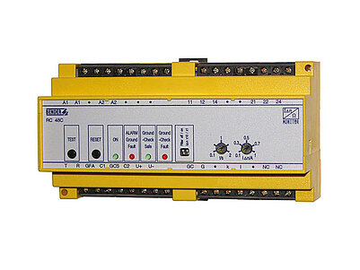
When this is the case, and ground-fault detection is a requirement of the system design, a supplemental ground-fault-protection device, typically a residual-current monitor, must be used.
Low-voltage adjustable-speed drives (up to 600 V) typically have a simple six-pulse rectifier input stage which creates a dc bus from which an inverter stage creates an output of controlled frequency and voltage. This output is used to control the speed of the attached motor and driven load for process control.
A core-balance zero-sequence current transformer (ZSCT), connected to a residual-current monitor, can be used to detect a ground fault in the drive, cabling, and motor. The zone of protection is downstream (load side) of the CT. If installed at the supply motor control center (location 1 in the figure), a ground fault in the motor and the cable between the motor and drive will also be detected.
This location provides the largest protection zone. If installed at the drive input (location 2), the drive is additionally included in the zone of protection. And, if installed on the drive load side (location 3), a ground fault in the motor and the cable between the motor and drive will be detected.
Variable-speed drives include semiconductor components such as diodes and IGBT’s, and have a dc-bus section. A ground fault in any of these elements is a dc ground fault. VFD’s are sometimes operated at very low speeds, and therefore a low output frequency, which will also be the fundamental frequency of a ground fault.
Typical residual-current-type ground-fault monitors cannot detect a low-frequency or DC ground fault—they are insensitive frequencies below 20 or 30 Hz. A system with VFD’s should include ground-fault detectors capable of low-frequency and DC fault detection. Specialized residual current relays using specialized current transformers are available to perform this function.
Variable-speed drives use semiconductor components to rectify and invert voltage and current. To create an AC output, the internal DC voltage is rapidly switched. This results in high-frequency voltage components which drive current through distributed system capacitance to ground—current that is not the result of a ground fault.
Simple broad-band-sensitive ground-fault detectors are fooled by these high-frequency signals and can falsely indicate non-existent ground faults if not set to a high value. This is easily avoided by using residual-current monitors that employ low- or band-pass filters that ignore the high-frequency noise.
In a low-voltage (typically 600 V or less) high-resistance-grounded (HRG) electrical power system, ground-fault current is limited to a low-enough level that the system need not be immediately tripped.
When configured as a pulsing system, the ground fault is located with the use of a hand-held clip-on ammeter. When applied upstream of the fault, the ammeter displays fault current. When not upstream of the fault, the meter can display leakage current. To differentiate between these readings, the pulsing circuit is enabled and “pulses” the ground-fault current, which is easily distinguished from charging current when observing the ammeter.
Bender can supply components such as the NGRM700 Neutral-Grounding-Resistor Monitor, which has a pulse-control function, and can supply a complete HRG system complete with pulsing control and ammeter.
| Name | Category | Size | Language | Timestamp | D-/B-Number |
|---|---|---|---|---|---|
| How to Size an NGR (US) | Technical Information | 424.0 KB | EN | 2019/05/1313.05.2019 |
Products
![[Translate to North American English:] NGRM700](/fileadmin/_processed_/3/b/csm_NGRM700_01_WEB_list_97278228d7.jpg)
Monitor for use in high-resistance grounded systems

Trailing cable protection, ground-fault ground-check monitor
![[Translate to North American English:] NGRM700](/fileadmin/_processed_/3/b/csm_NGRM700_01_WEB_list_97278228d7.jpg)
Monitor for use in high-resistance grounded systems

Trailing cable protection, ground-fault ground-check monitor