Automatic Fault Location
For Healthcare Facilities
- Easily identify system faults
- Locate faults while remaining operational
- Reduce downtime and save costs
Automatic Fault Location
For Healthcare Facilities
For decades, facilities have been burdened by the inability of traditional UL-1047 Isolated Power Systems and Line Isolation Monitors (LIM) to assist in determining which devices or circuits are causing faults and sending the LIM into alarm. Often, this would result in hours (if not days) of facilities troubleshooting to determine the root cause resulting in downtime of the operating room, rescheduling procedures in the process.
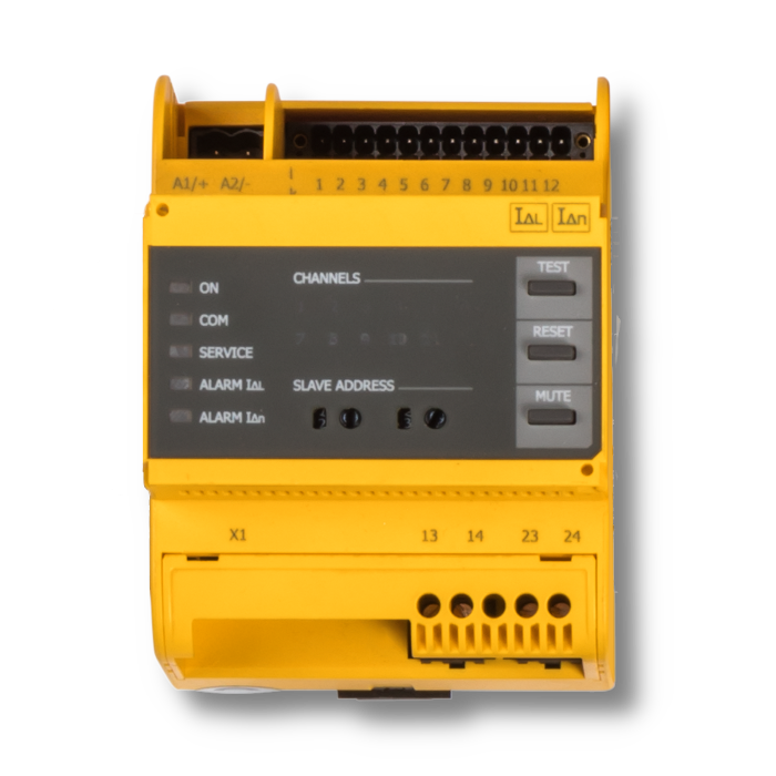
Bender engineers have developed a solution capable of immediately identifying which circuits contribute to a ground-fault on an isolated power system. Our fully automated ON-LINE ground-fault location systems (EDS Series) are designed to reduce operating room downtime and provide efficient troubleshooting, resulting in potential facilities savings of thousands of dollars per year. Find the faulty device and circuits within seconds.
With Bender’s advanced UL-1022 LIM2010, easily measure and calculate the Total Hazard Current (THC) and alarms when the defined threshold (5mA) is met. Once the THC and resistive fault threshold is achieved, the LIM’s integral fault location system is activated. The LIM2010 next sends out a tracer pulse which is detected by the ultra-high sensitivity current sensors associated with each branch circuit and evaluated by the EDS modules. Once found, the EDS module will illuminate LEDs corresponding to the problem circuits. With the automatic fault location system, circuits with resistive type faults can be identified with indication locally on the face of the fault location monitor and in plain text on a remote display. Such functionality hastens fault finding efforts, increasing OR availability. Additionally, when paired with Bender’s communication modules, both alerts and realtime data can be integrated into the facilities central BMS and/or received via email/text message to hospital maintenance technicians.
In the illustration, we show a resistive ground fault occurring on Circuit No. 2 of the Isolated Power System. When this occurs, the LIM measures the resulting change in system impedance, calculates the THC, and displays a “Hazard” message. Next, the LIM generates a tracer pulse that is detected by the current sensors. Seconds later, the EDS evaluates the signals detected by the current sensors and indicates exactly which circuit has the fault locally on its display. The information is then transmitted via the systems (RS-485) communication bus and displays a message in plain text on a remote indicating device.
| Name | Category | Size | Language | Timestamp | D-/B-Number |
|---|---|---|---|---|---|
| EDS440/EDS441 | Datasheets | 3.5 MB | EN | 2026/02/2424.02.2026 | D00201 |
| EDS441-LNA-KITS Datasheet (US) | Datasheets | 4.7 MB | EN | 2024/02/2727.02.2024 | D00201 |
| EDS - Automatic Fault Location | Flyers | 1.1 MB | EN | 2021/04/2828.04.2021 | |
| Infographic: Simple Solution for Fault Detection | Flyers | 261.4 KB | EN | 2020/05/2222.05.2020 |